Automating surface finishing has never really been about the robot. It's about the path: where the end effector goes, how it touches the surface, and whether that trajectory is safe before anyone presses start.
In the first part of our video tutorial, we look at how a path comes to life inside SUPERO OS.
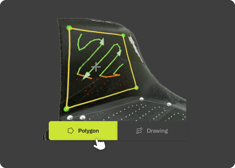
The digital twin as a workspace
Path generation starts from the colour 3D model acquired during Step 1: the digital twin of the component, already cleaned and optimised by the system.
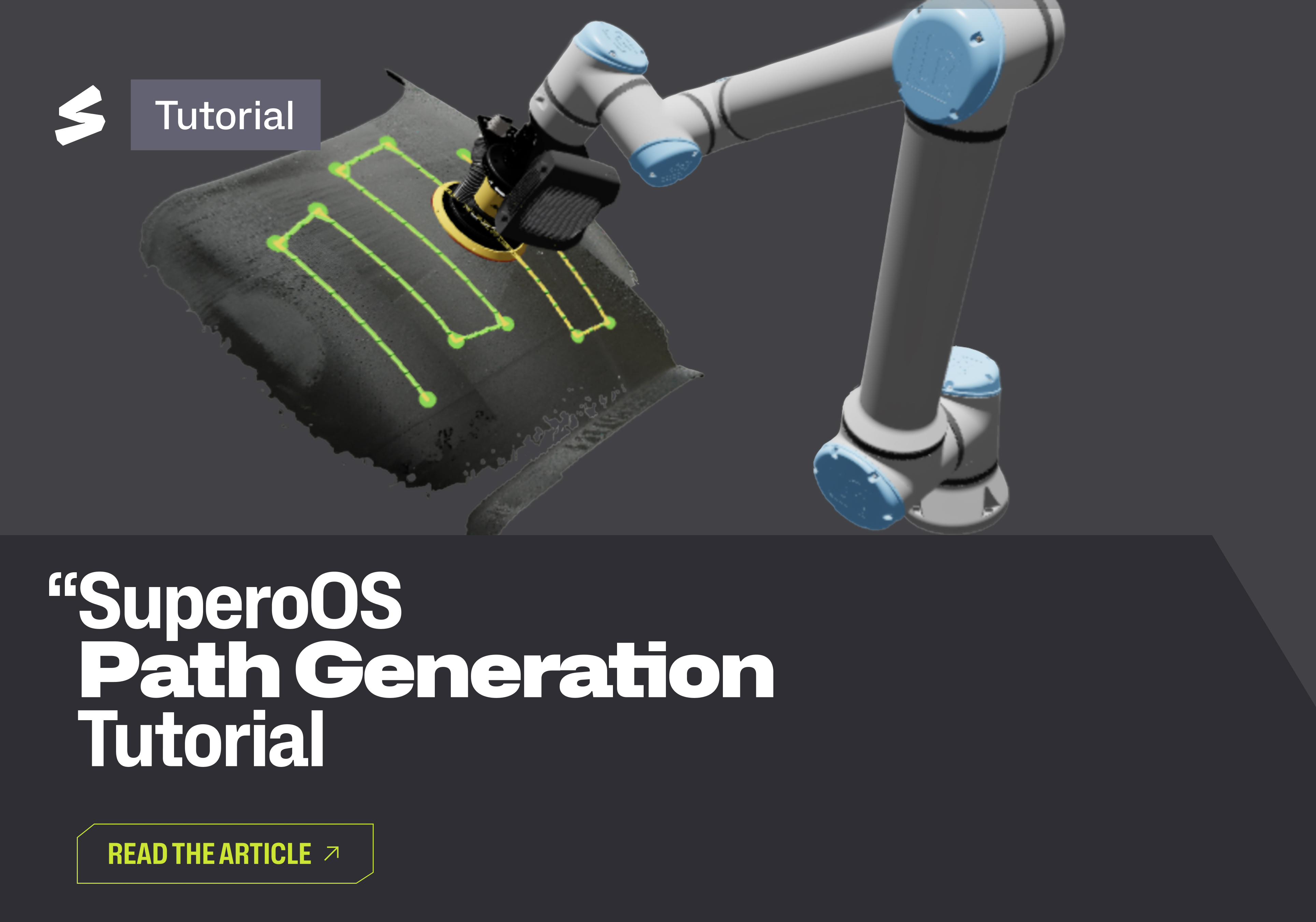
From there, the operator draws directly on the surface. A polygon traced with the mouse is enough to identify a region of the part: that polygon stays fully editable, vertices can be moved to follow the geometry, and the whole shape repositioned while keeping its profile. Once the area is defined, the toolpath is generated and the simulation previews the trajectory on the surface.
No offline programming, no CAD/CAM round-trip. This is exactly what makes Supero suited to the unknown and variable geometries of high-mix production: the process is defined where it actually happens, on the part.
Automatic by default, manual when needed
SUPERO OS applies a set of automatic parameters from the start, enough to obtain a valid path in a matter of seconds. It's the working smarter, not harder philosophy: the system does the work, the operator makes the calls.
But finishing is rarely one-size-fits-all. The automatic parameters can be switched off at any time, handing over full control of the machining strategy: the zig-zag spacing defines the surface coverage, the boundary offset adjusts the distance of the path from the edges of the polygon, and in polygon mode the path can also be laid out as parallel lines instead of the classic zig-zag.
Two settings deserve a separate mention, because they are the point where robotic finishing comes closest to the craft it replaces:
- the contact point, which determines which portion of the abrasive end effector actually comes into contact with the surface — essential when a region has to be worked with a specific part of the end effector;
- the attack angle, the angle at which the end effector engages the part.
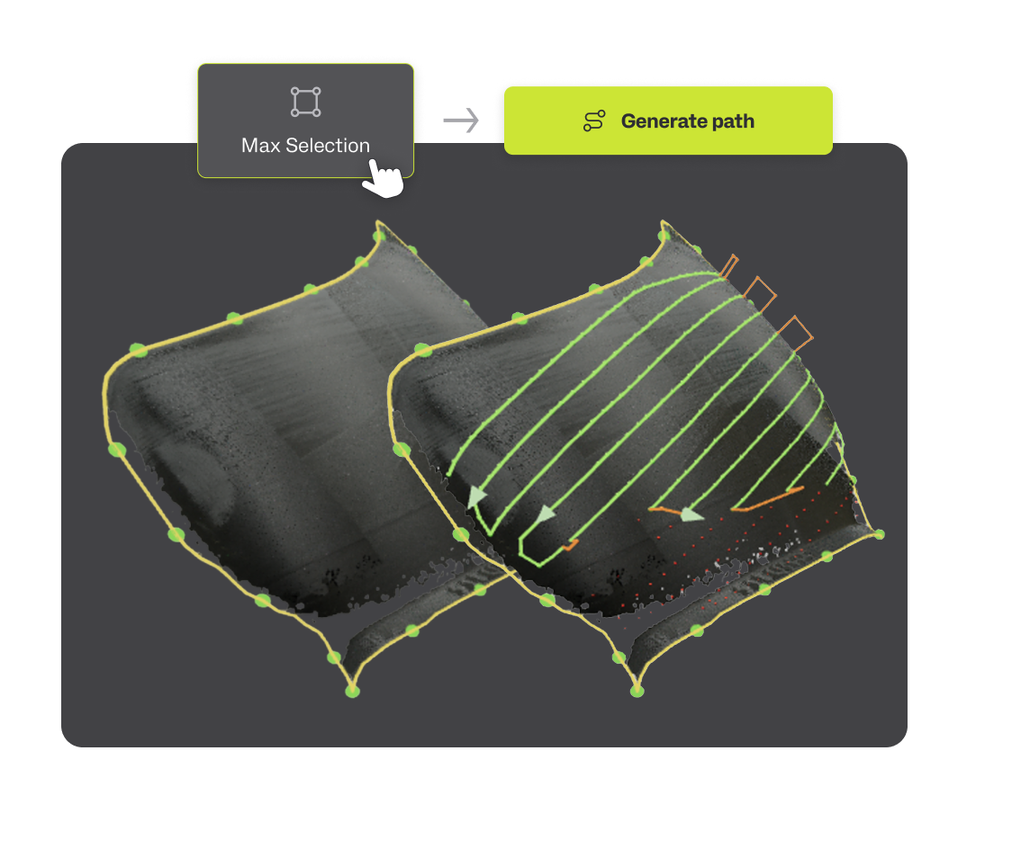
Coverage you can see
Once the path is generated, the simulation shows the trajectory on the digital twin, with the contact state displayed on the path itself: green while the end effector is working on the surface, orange when it lifts off and is no longer in contact.
For larger surfaces, max selection picks up an entire continuous region of the part — a full hood, for example — with a single action. The toolpath is regenerated to cover the whole selection, and the simulation verifies the coverage.
Safe before it becomes real
Before execution, SUPERO OS validates every path in real time: it checks for collisions, reachability and singularities, so the robot only moves through configurations it can genuinely reach in safety.
The result is readable at a glance, directly on the path:
- green: the path is safe and the end effector is in contact with the surface;
- orange: SUPERO has inserted a bridge to cross regions that are unreachable or at risk of collision;
- red: the path is unsafe and needs correcting.
It's validation you can see, not a report you have to interpret.
Defining a path in SUPERO OS isn't programming a robot: it's describing a job. The operator draws the area, chooses how the end effector should touch the surface, and the system takes care of the rest — validation included.
Discover how to automate your industrial production with Supero and watch the full video here.